I make stuff

screenshot
◄ Previous article Next article ►

AV-Racer Devlog (3): Designing the AI

Thursday, May 19, 2022

est. reading time: 9 minutes

As explained in the previous article, the maps include node and spline data for an AI line to follow. The line runs through the track and is meant to guide steering. Having that, the first step to take is to figure out how to make the AI follow the line.

node segment 
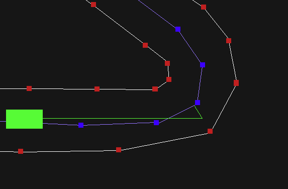
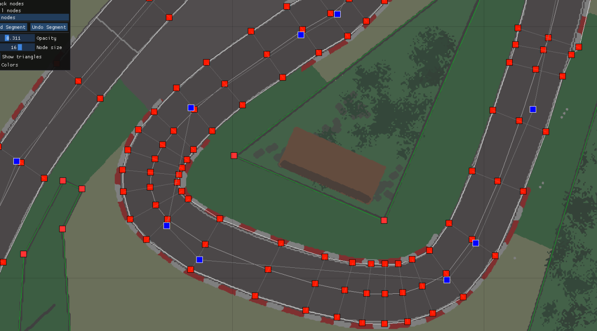
The nodes are in blue. Connecting them is the AI line.

The AI input can be summed up in two main categories: The first is steering, the second is gas and brake input. I decided to tackle the steering first.

Steering

The first and most basic model I thought to implement was a node-oriented steering model. The idea is that a simple vector is calculated from the car's current position to the nearest node on the track. Then an angle is calculated between this vector and the car's longitudinal vector pointing forward. The resulting angle determines how much the car would steer left or right. The steering angle is then capped to 45 degrees.

There were a few prerequisite calculations to get this right. To know where the nearest node is, we would have to loop over all nodes on track, and check where the nearest is. However, this would mean the car would go to the nearest node regardless where it was on the track. So, if that nearest node was on a nearby road parallel to the road the car is on, then the AI would drive itself into a wall; not exactly ideal.

A better algorithm would have us know the current AI node the car is on. Then, relative to that, we get the next node on the track. This will guarantee the car doesn't try to cut the track to the wrong nodes, or even worse, start driving backwards. To know what node we are on we can refer to what segment of the track we are on, and if we are on the same segment as a certain node then we are at that node more or less. This works since track segments are relatively small, as cerated with the map editor.

Getting the car's position:

Below is code from the game on how that is done:


    float TriangleArea(v2 A, v2 B, v2 C)
    {
        return abs((A.x * (B.y - C.y) + B.x * (C.y - A.y) + C.x * (A.y - B.y)) / 2.0f);
    }

    bool PointInTriangle(v2 P, v2 A, v2 B, v2 C)
    {
        float A1 = TriangleArea(P, B, C);
        float A2 = TriangleArea(P, C, A);
        float A3 = TriangleArea(P, A, B);
        float AA = TriangleArea(A, B, C);
        return abs(A1 + A2 + A3 - AA) < 0.00001f;
    }
    bool PointInNodeSegment(v2 *P, tracknode *A, tracknode *B)
    {
        bool a = PointInTriangle(*P, A->L, A->R, B->L);
        bool b = PointInTriangle(*P, A->R, B->L, B->R);
        return a || b;
    }

    ....    

    static void UpdateCarOnTrack(int p)
    {
        v2 P = G->Car[p].P;     
        bool is_on_track = false;
        for (int t = 0; t < G->Track.T_NodeCount - 1; t++)
        {
            if (PointInNodeSegment(&P, &G->Track.T_Nodes[t], &G->Track.T_Nodes[t + 1]))
            {
                is_on_track = true;
                G->Car[p].trackpos = t;
            }
        }
        G->Car[p].ontrack = is_on_track;
    }

    
The function UpdateCarOnTrack() above gets the current track position of the car and checks if it is on the track. That information is useful for other effects like the car's grip and emulation of a dirt/ asphalt surface. The track position information also helps sorting car positions on the live leadboard according to relative track positions.
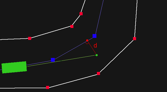
The PointInNodeSegment() runs a basic algorithm where every two track nodes are taken and the car position is checked whether it is between them. Since each track node has a left and right points defining the road, we can check if the position is within either of the two triangles formed between the four points of the two node groups. This is done using a method that determines if a point is inside a triangle PointInTriangle() which calculates the areas formed between the point in question and all two pairs of points defining a triangle. When comparing areas one could predict if the point is inside, outside, or on the triangle. I use < 0.00001f to account for floating point calculation errors. The method isn't the most efficient but the calculations weren't many per frame (~250 track nodes per track, and a maximum of 10 cars = ~2.5k calculations per frame. It was fine). Here's how it works:

triangles node segment

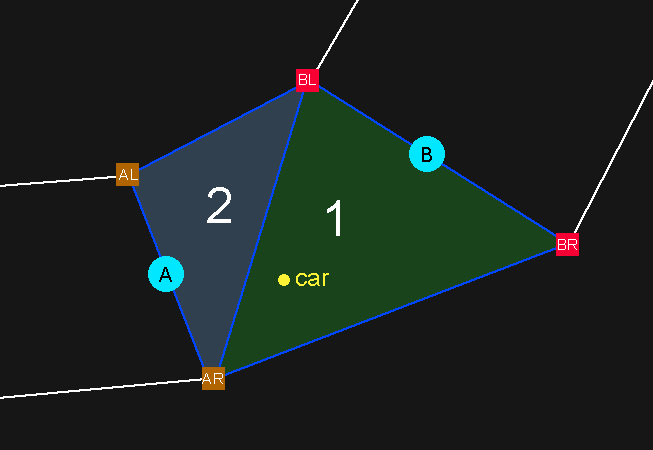
Triangles (1) and (2) in the picture are formed between (A)'s and (B)'s respective left and right node points. The two triangles form a 'Segment'. In this case, the car is on triangle (1) so it is between the nodes (A) and (B), so it is at the track node (A). Determining which triangle it is on is therefore irrelevant.

Now we have an algorithm that can determine what part of the track a point is on, we can use it on the AI nodes. Knowing where the AI nodes are can then help us know where the nearest one to the car is, relative to the car's position. It would be wasteful, however, to run this algorithm every frame on all the AI nodes like we do on cars. The AI nodes are predetermined and static, unlike moving cars. So, it is best to precalculate the data of where every AI node on the track is. We can do this at the track loading phase and store that data statically for reference.

1- Spidey Model v1:

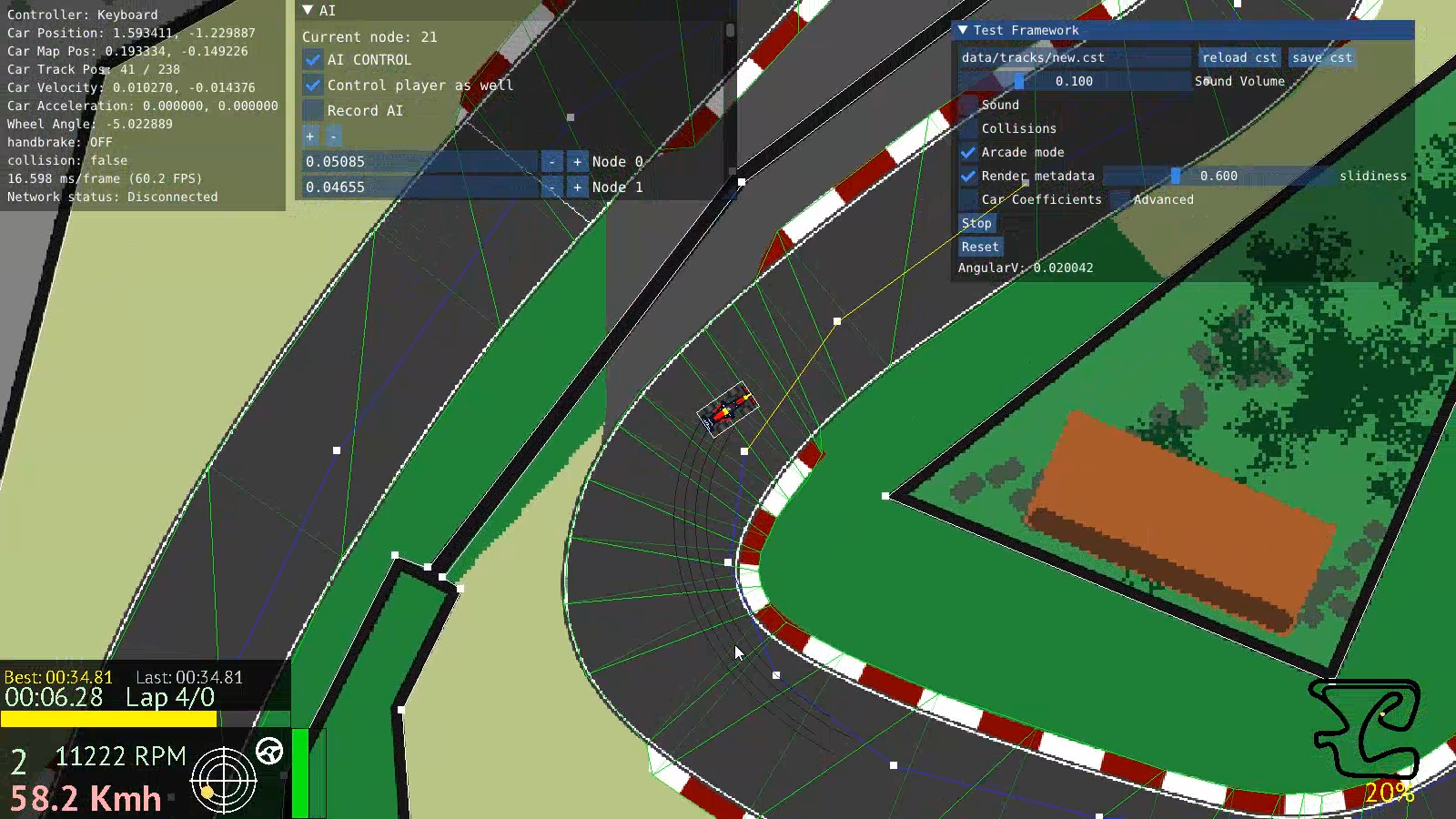
Now that we have the data we need we can use the AI steering algorithm mentioned at the start and apply it to the car. The result looks as follows :

(the car's throttle input is controlled through keyboard in this example and the steering is controlled by the AI)

I call this the Spidey Steering AI Model (patent pending). As you can see, the car seems to swing from one node to the other, the actual spline of AI line is rendered meaningless as the car erratically slides left and right to follow the nodes. The car could successfully finish a lap but setting up the nodes correctly to accommodate cornering and sliding without hitting obstacles was very tedious. It took up to an hour of tuning the node locations to get the result above. This was not sustainable. The model proved especially weak when it came to complex corners in a series of curves. There was no way to fine tune the driving line the car took to account for multiple corners ahead. So I went back to the drawing board and tried something new.

2- Spidey Model v2:

Still using the same idea, the new model would calculate the turn angle based on the next two nodes instead of the next node alone. The average angle between the car and each of the nodes is taken. The result was somewhat better as there was more consistency with looking somewhat ahead. Here:


The car now seems to anticipate turns if the nodes were placed right, but that was the problem. Placing the nodes right was a nightmare and it never achieved a good driving line. Plus, this model would start failing if we had more than two simple nodes in a row. This whole approach was not viable for the complexity of tracks I had in mind. Either I make the tracks simpler or the AI more sophisticated, I decided on the latter. So, back to the drawing board again.

3- Point Projection Model:

The method I used next shifts the focus from the nodes to the lines between the nodes. In the end, it's called an AI line. Starting from the car's position we project a forward vector of an arbitrary length in the direction of the longitudinal axis of the car. The Line then has a point at its end, from which we can drop a projection of that point perpendicularly onto the nearest AI line (dot product) measuring the shortest distance to the line:

look ahead projection

The distance 'd' can be used to determine the steering angle of the car. This method produces much more consistent driving lines and makes the drawing and fine tuning of the AI lines much easier in the track editor. We can further improve on the model to handle cases where the projected point or the car might be offtrack, here we can simple flip back to the Spidey model and the car will just try to to get to the closest node until it is back on track. The result is as follows:


Now that is more like it! The car seems more sensitive to the AI line and the behavior looks more organic.

Further Improvements:

The model could still be improved though. We can make the projected vector proportional to the car's velocity, so that the faster the car is the further ahead it looked.

One problem with a projection, however, is that since the node line segments aren't uniform, the projection looks ahead inconsistently. To fix the issue, we can take the length of the projected line and subtract the next segment's length from it, if the remainder is larger than zero we subtract the next node, and so on until we reach zero or lower. That's the "target" segment we test on. Here's a demonstration, imagine the car approaching fast with a long projection line but is faced with a sharp corner:

look ahead projection 2

Targeting the right segment this way produces more consistent AI behavior with variable speeds. But what if the line went far beyond and couldn't project on the right segment at a sharp turn? Like this:

look ahead projection 3

Projection here would give wrong results. We can then couple this with the Spidey model to handle cases where the car or the projected point are offtrack. Here, the car simply points to the target AI node producing correct turning at high speeds.

PID Controller:

The PID controller (proportional - integral - derivative controller) is an algorithm that uses the derivative and integer of a certain function that takes continuous adjustment to produce a smoother output. When the car is turning it is constantly adjusting and recalculating which can sometimes produce oscillating behavior when the adjustment overshoots. The PID controller helps smoothen the oscillation to a gradual curve. The algorithm is surprisingly simple, here's how it works in the game:


struct pid_controller
{
    float Kp;
    float Ki;
    float Kd;

    float integral = 0;
    float last_error = 0;
    float last_time = 0;
};

...

 float UpdatePID(pid_controller *PID, float error, float dt)
{
    PID->integral += error * dt;
    PID->integral = sign(PID->integral) * clamp(abs(PID->integral), 0.0f, 50);

    float derivative = (error - PID->last_error) / dt;
    PID->last_error = error;
    PID->last_time = dt;

    return PID->Kp * error + 0.001 * PID->Ki * PID->integral + PID->Kd * derivative;
}

Basically every AI car has a PID controller struct which saves information like the last error, time, accumulative integral and the three constant coefficients we adjust through testing. (usually Ki and Kd are half of Kp). We input the "error" which in this case is the distance between the projection the nearest AI line segment. We then use the output to adjust steering. This significantly smoothens the AI steering behavior.

Throttle and Brake

If we look at how we handled steering, we can see that the system relies on a premade AI racing line which represents the steering data. It then uses that as a reference to adjust the car's angle. Throttle and brake input, however, does not have an AI line of their own, as that information cannot be drawn in the editor. Generating correct throttle and brake input was also not a realistic option as it required much more complex AI design to handle predicting optimum corner speeds on the go. So in order to make an AI "speed line", we could just record the car's speeds at each node. The problem turned out to be much simpler than I initially anticipated. 
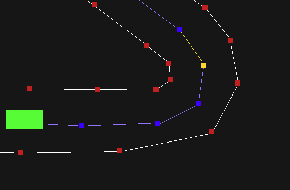
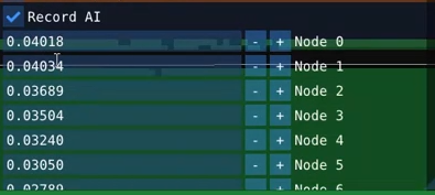
Since the whole game takes place in premade tracks, there is really no real reason to create any "smart" AI pathfinding algorithms. The AI will just follow the AI line and drive at the speed it was recorded at. So I implemented a record functionality and an array of AI node speeds stored in the track metadata, each time I create a new track, I run the AI with it while controlling throttle and brake input myself while the game records the speeds. That info then gets saved on the track file. When playing, a very simple algorithm compares the current speed to the one recorded adjusts the car's inputs, producing very usable results.

record values

Putting all of this together, we get the following:


Smooth steering and throttle input, good AI line, and competitive lap times. The AI looks good!

Overtaking algorithms

Now if we put the cars in this current state in the game, they will sooner or later form a train and follow each other, no overtaking happening. We need some action!
Since this game is an arcader and it is not necessary to have any complex collision avoidance or driving etiquette, we can make the cars just aggressively drive around each other, and sometimes into each other, while trying to overtake.

For this, each car checks in front of it if a projected line intersects another car, and if it does, it locks onto the target car flipping to an overtake mode. Here, the car looks at the target car in front of it and checks whether the target is closer to the left or right side of the track, then it turns to the opposite side where there's an opening, aiming to the side nodes of the track instead of the AI line nodes. This makes the car take an outside or inside line around corners. This simple check produced very interesting overtaking action in the game, and was enough to cover its arcade purposes.

As you can see, the cars now overtake each other, and produce enough variable action to make the game interesting and challenging.

All of these different algorithms can be modified by a difficulty system. The AI driving lines and cornering speeds are initially tuned to produce really fast lap times. The PID controller's coefficients and the recorded track node speeds could then be scaled down with the difficulty level. The overtaking algorithm stays the same, as there is no need to change it.

Thank you for reading all of this, I hope this could be useful for you. I hope you enjoy the game!

-Wassim